Turnstile Gate Installation: Step-by-Step Guide from Site Prep to Commissioning
2026-04-11
Most turnstile gate installation problems do not come from faulty hardware. They come from poor site preparation, rushed wiring, skipped testing, and misconfigured parameters that turn a reliable gate into a daily source of nuisance alarms and access failures. Getting the turnstile gate installation process right from the beginning — before any hardware is unpacked — determines whether the gate runs smoothly for years or generates maintenance calls within weeks.
This guide walks through every phase: site preparation, gate-type considerations, step-by-step installation, cable and reader wiring, commissioning parameters, and the post-installation maintenance schedule that most project teams ignore until something breaks.
What Determines Turnstile Gate Installation Complexity?
Not all turnstile gate installation projects are the same. Complexity scales with gate type, floor construction, credential reader count, lane volume, and whether the installation is indoor or outdoor.
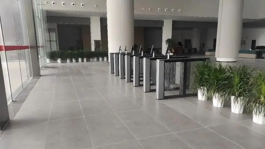
A single tripod turnstile on a concrete floor with one RFID card reader is a half-day installation for an experienced two-person team. A six-lane speed gate deployment on a raised marble floor with QR scanners, face recognition terminals, and cloud platform connection is a multi-day project requiring advance cable routing, floor cutting, and controller configuration across multiple gate units.
Understanding what drives complexity helps you plan the right project timeline, assign the correct team, and order site preparation work in the right sequence. The access control turnstile gate solutions page covers available gate configurations and their typical deployment environments — useful context for scoping installation requirements before site work begins.
Tools and Equipment You Need Before Installation Begins
Arriving on site without the right tools is the fastest way to turn a planned four-hour installation into a two-day problem. Gather everything listed below before any hardware is transported to the installation location.
Physical installation tools:
- Hammer drill with 12mm and 16mm masonry bits
- M12 or M16 expansion anchor bolts (quantity matching mounting holes per gate unit)
- Torque wrench for anchor bolt tightening
- Spirit level (minimum 600mm for gate cabinet alignment)
- Measuring tape and chalk line for lane spacing
- Shims or leveling plates for uneven floors
Electrical and cabling tools:
- Cable strippers and crimping tools
- Multimeter for voltage and continuity testing
- Wiring labels and cable ties
- Conduit bender and pulling tape if cables run through new conduit
- Earthing/grounding wire and bonding clamps
Safety and documentation:
- Circuit breaker on the power feed with correct amperage rating
- Installation manual and wiring diagram for the specific gate model
- Camera for documenting cable routing before floor or wall covering goes over it
Site Preparation: The Phase That Decides Everything
Site preparation is the phase that most project teams underestimate — and the one that causes the most installation problems. A properly prepared site makes the hardware installation fast and reliable. An unprepared site creates problems that no amount of commissioning can fully correct.
Floor condition and leveling
The gate cabinet must sit on a flat, level surface. Most gate manufacturers specify a maximum floor tolerance of 2mm across the cabinet footprint. A floor with a slope or high point under the cabinet creates misalignment between opposing gate units in a multi-lane installation. Misaligned units mean uneven passage channels, abnormal wing wear, and — in speed gate installations — glass panel contact with the cabinet housing. Address floor leveling before any hardware arrives on site.
Conduit and cable routing
All power, signal, and communication cables should be routed in floor conduits or wall trunking before gate installation begins. Mark cable exit positions on the floor based on the gate cabinet's base drawing. The floor outlet hole center should align with the center of the gate cabinet base. For multi-lane deployments, label every cable at both ends before closing conduits — finding an unlabeled cable in a six-lane installation after the floor covering is down costs hours of troubleshooting time.
Power supply specification
Confirm the power supply voltage matches the gate's specification — typically 110V or 220V AC. Run a dedicated circuit for the gate system rather than tapping into a shared circuit. Voltage fluctuations from shared circuits cause control board errors and intermittent sensor faults. Confirm the circuit breaker rating matches the combined current draw of all gate units in the installation plus a 20% safety margin.
Grounding
Every gate cabinet requires a direct earth grounding connection. Poor grounding is the most common cause of electromagnetic interference that triggers false sensor alarms and causes control board erratic behavior — particularly in buildings with variable power quality or industrial electrical environments. Run a dedicated ground wire from each cabinet to a confirmed earth bonding point.
Gate-Type-Specific Installation Considerations
Different gate types have different site and installation requirements. Matching your preparation to the specific gate type saves time and avoids surprises during the installation phase.
Compact Swing Gate
The compact swing gate turnstile suits narrower entry points and ADA-compliant wide lanes. Installation requires careful clearance measurement on both the hinge side and the swing arc radius — the full panel swing path must be clear of walls, pillars, columns, and any furniture within the operational arc. Floor anchor points are typically at the rear base of the cabinet. Swing gates in wide-lane configurations also need the opposing wall or barrier panel anchored to resist the door swing force.
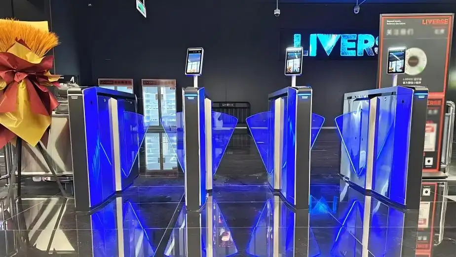
Glass Sliding Gate
The glass sliding gate turnstile requires the most precise floor preparation of any gate type. The sliding panel's guide track must sit in a perfectly straight, level floor channel. Any deviation in the track alignment creates glass-to-housing contact during operation. Mark and check the guide channel line with a chalk snap line before cutting. Allow adequate clearance at the panel retraction end — the full panel width plus 50mm clearance in the retraction direction.
Dual-Arm Tripod Turnstile
The dual-arm tripod turnstile gate is the most installation-friendly gate type. The compact footprint requires four anchor points, and the low cabinet height makes cable routing through the base straightforward. For multi-lane tripod deployments, maintain consistent spacing between units — typically 550mm to 650mm passage width — and check that opposing arms across the lane gap do not make contact during rotation. Anchor all units to the floor before connecting any cables to avoid vibration shifting during the anchor bolt tightening phase.
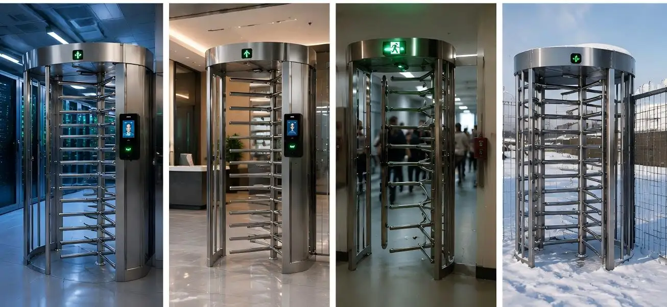
Full-Height Turnstile
The full-height turnstile gate is the heaviest gate type and requires the most structural floor preparation. Most full-height units weigh 150kg to 300kg — confirm floor load capacity before installation, particularly on raised floors or decked surfaces. The rotor arms extend 800mm to 1000mm from the cabinet center, requiring clear overhead and side clearance during full rotation. Anchor the base plate with a minimum of six M16 expansion bolts torqued to specification. Full-height units installed outdoors require a concrete plinth of minimum 200mm depth for anchor hold in the outdoor substrate.
Step-by-Step Turnstile Gate Installation Process
With site preparation complete and all tools confirmed, the physical installation follows a consistent nine-step sequence regardless of gate type.
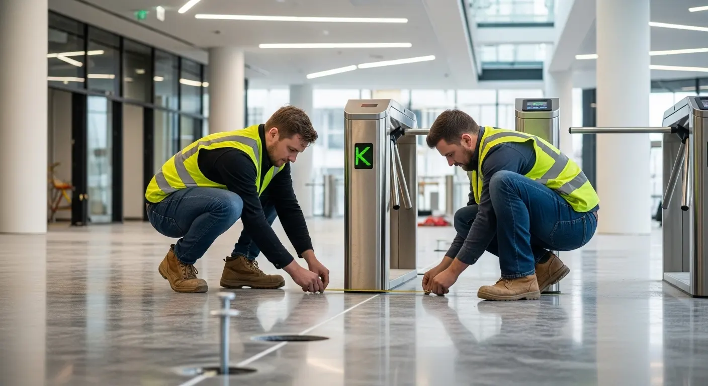
Step 1 — Confirm final positioning. Place each gate cabinet in its intended position using the architectural layout drawing. Check spacing between adjacent units for consistent passage width. For multi-lane installations, set all units in position before marking any anchor points — this catches layout errors before holes are drilled.
Step 2 — Mark anchor hole positions. With each unit level and correctly positioned, mark the anchor hole positions through the cabinet base onto the floor. Remove the cabinet, double-check all marks are aligned with the layout drawing, then mark center points for drilling.
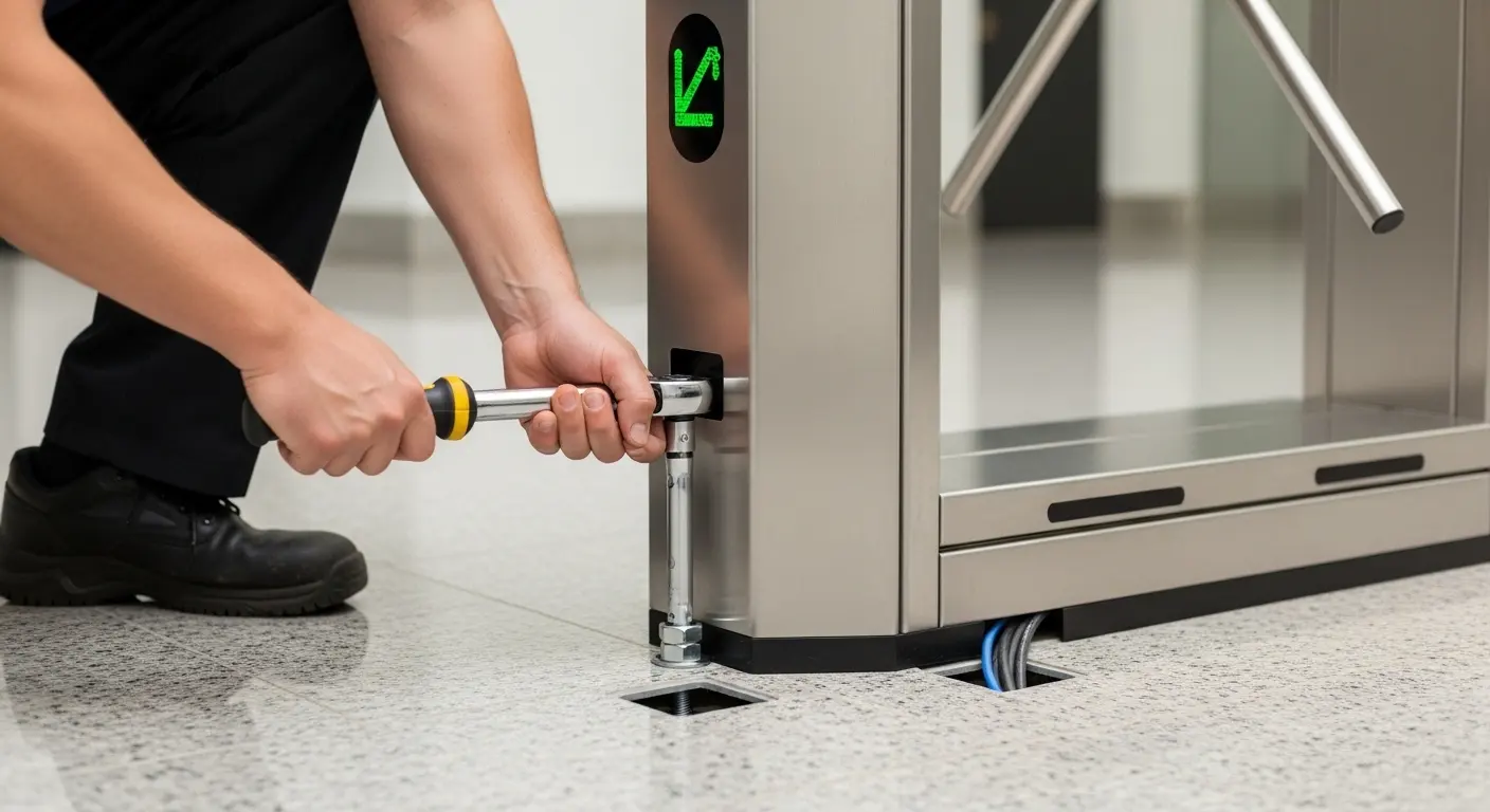
Step 3 — Drill and set anchor bolts. Drill anchor holes to the depth specified for the anchor bolt type — typically 100 to 130mm for M12 expansion bolts. Clear debris from holes, insert expansion bolts, and partially tighten. Do not fully torque at this stage — final torquing comes after the gate is placed and leveled.
Step 4 — Place and level the gate cabinet. Lower the cabinet onto the anchor bolts. Use a spirit level to confirm the cabinet is perfectly horizontal and vertical in both axes. Use shims under the base plate if minor floor irregularities require correction. Once level, tighten anchor bolts to the torque specification in the installation manual.
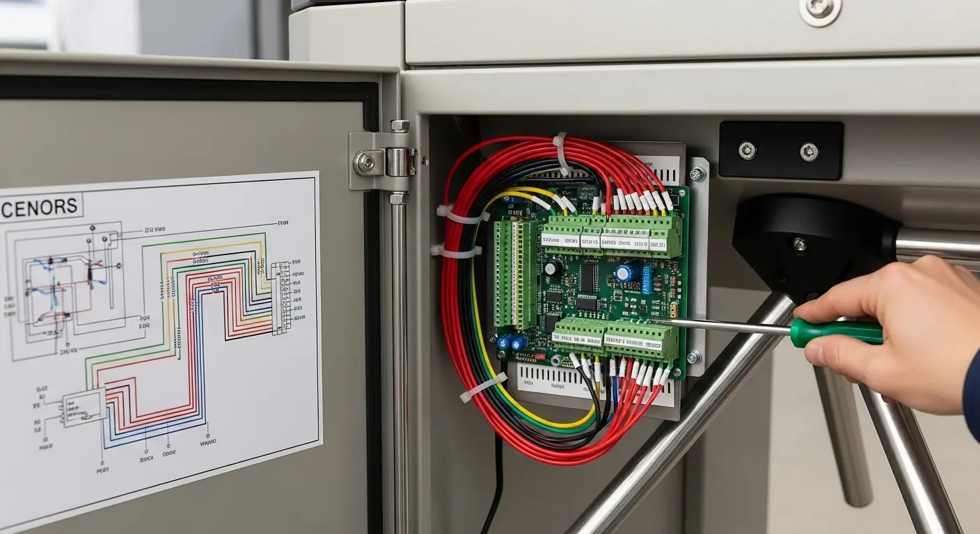
Step 5 — Route and connect cables. This step requires the most care. Open the access panel to expose the control board. Connect power first — main power cable to the terminal block with correct polarity and ground. Then connect access control reader cables, exit button wires, and alarm outputs to their designated board terminals. For multi-lane installations, connect the SYNC cables between adjacent units and the network cable to the controller or cloud gateway. Always follow the wiring diagram specific to your gate model. A single incorrect terminal connection at this stage can damage the control board.
The support video page includes model-specific installation and wiring walkthrough videos — a practical reference to check cable connection points before powering on for the first time.
Step 6 — Initial power-on. Apply power and observe the control board LED indicators during the self-test cycle. The gate will open and close several times during self-test — confirm no one stands in the passage lane during this phase. A green board status indicator after self-test confirms normal startup. Any error code at this stage indicates a connection fault before the gate has operated under user traffic.
Step 7 — Configure operating parameters. After successful self-test, set operational parameters via the control board menu or connected software. Key parameters: opening and closing speed, passage direction (one-way, two-way, free exit), anti-pinch sensor sensitivity, passage time window (seconds between credential scan and expected passage), alarm condition thresholds, and auto-close timer.
Step 8 — Test all credential types and safety functions. Test the gate with every authentication method planned for the deployment — RFID card, QR code, fingerprint, or face terminal. Test anti-pinch by gently obstructing the closing panel with a test object. Test emergency fail-safe or fail-secure mode by cutting power and confirming the gate responds per the specified mode. Test anti-tailgating detection by attempting to pass two people on one credential scan.
Step 9 — Final inspection and handover. Fasten all access panels and covers securely. Clean the cabinet surface with a dry cloth. Walk the lane multiple times to confirm natural pedestrian flow. Label each gate unit and lane with its physical ID matching the system configuration. Document cable routing photographs and hand over the installation record to the facility manager before leaving site.
Wiring and Credential Reader Connection Guide
Credential reader wiring is the step where most commissioning problems originate. Each reader type connects to the control board differently.
RFID card reader: Most RFID readers output Wiegand 26 or Wiegand 34 signal. Connect the green wire (DATA0) and white wire (DATA1) to the corresponding Wiegand input terminals on the control board. Red wire connects to 12V power, black wire to GND. Confirm Wiegand format matches the board's configured input format.
QR/barcode scanner: Most barcode reader modules output via RS232 or USB. RS232 connections use TX, RX, and GND terminals. If the control board accepts only Wiegand, a Wiegand-output scanner or a signal converter is required. Confirm output format compatibility before ordering scanner hardware.
Face recognition terminal: Face terminals typically connect via TCP/IP network cable to the access controller or cloud platform — not directly to the gate board's Wiegand terminals. The gate board receives a dry-contact relay signal from the terminal on authentication success. Connect the relay output of the face terminal to the gate board's access input terminals, observing normally-open vs. normally-closed contact configuration.
Multi-lane SYNC cable: In multi-lane deployments, a SYNC cable connects opposing gate units in each lane pair. This cable synchronizes gate opening between the entry and exit cabinets. Confirm SYNC cable polarity — reversed SYNC wiring causes opposing panels to close instead of open on credential verification.
Commissioning Parameter Configuration
After power-on and wiring verification, parameter configuration determines how the gate behaves under real operating conditions.
Opening and closing speed: Higher speeds suit high-volume transit environments. Slower speeds suit corporate lobbies, hospitals, and environments where user populations include older adults or visitors unfamiliar with turnstile gates. Start at a medium speed setting, observe live traffic during the first peak period, and adjust based on actual throughput rhythm.
Passage time window: This is the time in seconds between a valid credential scan and the expected completion of passage. If the window is too short, users who pause to retrieve a bag or check their phone fail the passage and trigger an alarm. If too long, a second unauthorized person can follow through during the window. For most corporate environments, 3 to 5 seconds is a practical starting range.
Anti-pinch sensor sensitivity: The gate's infrared anti-pinch sensors stop panel closure when an obstruction is detected in the passage beam. Setting sensitivity too low misses small objects. Setting it too high causes false-stop events from ambient light interference. Test under actual site lighting conditions during commissioning, not just in an empty lobby at night.
Alarm conditions: Configure alarm output for: unauthorized entry attempt, anti-tailgating detection, reverse passage attempt, passage overtime (user who enters the lane but does not complete passage within the time window), and power fault. Connect alarm output to the site security management system if available.
Common Turnstile Gate Installation Mistakes
Installing on an unleveled floor without shimming. Even a 3mm slope under the cabinet creates misalignment that compounds over time — gates in misaligned installations show abnormal wear on panel hinges, bearings, and motor coupling within 6 to 12 months. Level the floor before the gate arrives, or use precision shims during installation. Never rely on tightening the anchor bolts to compensate for floor irregularity.
Wiring cables before anchoring the cabinet. Connecting cables to the control board before the cabinet is fully anchored and torqued means every adjustment movement risks pulling or straining connected terminals. Anchor fully first, then open the access panel and connect cables.
Skipping the load test of the verification backend. A gate that opens perfectly during a 10-person commissioning test may show credential verification latency when 200 people scan across 8 lanes simultaneously during a morning peak entry. Load-test the backend API or access control server under simulated peak traffic before handing the system over to the client.
Configuring incorrect passage direction settings. A reversed entry/exit direction parameter means a credential scan grants access in the wrong direction — or triggers an alarm on a normal exit. Test both passage directions with a physical body before confirming parameters are set correctly.
Not documenting cable routing before floor finishing. Once floor tiles, carpet, or raised floor panels go over cable conduits, the routing is invisible. If a cable fault develops later, undocumented routing means cutting open the wrong floor section. Photograph all cable routes before any surface finishing covers them, and include the photographs in the installation handover file.
Post-Installation Maintenance Schedule
A well-installed turnstile gate installation needs structured maintenance to stay reliable. Most gate failures are preventable with routine checks on a defined schedule.
Weekly:
- Visual check of panel surface, LED indicators, and gate housing condition
- Confirm green/red direction indicators respond correctly on test credential scan
- Check for visible debris or objects lodged in the infrared sensor path
Monthly:
- Clean stainless-steel housing panels with mild stainless cleaner and dry cloth
- Visually inspect anchor bolt heads for any sign of floor movement or loosening
- Test anti-pinch function by obstructing a closing panel with a test object
- Confirm emergency fail-safe or fail-secure mode operates correctly on power cut test
Quarterly:
- Apply light lubrication to rotating arms, hinge pins, and motor coupling joints per manufacturer specification
- Check infrared sensor alignment — transmitter and receiver alignment drifts on gates in high-vibration environments
- Review access control event log for unusual denial rates or repeated individual failures that may indicate a sensor drift or reader configuration issue
- Clean credential reader windows and camera lenses with a dry lint-free cloth
FAQ: Turnstile Gate Installation
How long does a turnstile gate installation take?
A single tripod turnstile on a prepared concrete floor takes 2 to 4 hours for an experienced two-person team, including cable connection and commissioning. A flap barrier or speed gate installation for a two-lane entry takes 4 to 8 hours. Multi-lane installations of 4 or more units typically require 1 to 2 full working days, depending on floor preparation quality, credential reader complexity, and backend system connection requirements. Site preparation — conduit routing, floor leveling, power supply installation — is separate from gate hardware installation time and should be completed before hardware delivery.
What floor preparation is needed before turnstile gate installation?
The floor must be level within 2mm across the gate cabinet footprint. Power conduits and signal cable conduits must be routed and terminated at floor exit positions aligned with the gate cabinet base layout drawing before installation begins. A dedicated power circuit with a correctly rated breaker should be installed and confirmed live before the gate arrives. For outdoor installations, a concrete plinth of minimum 150 to 200mm depth provides the anchor hold required for full-height and heavy flap barrier units.
Can I install a turnstile gate without a professional installer?
Physically positioning and anchoring a turnstile gate is within the capability of a skilled maintenance team with the right tools. The critical steps that require electrical knowledge are: power cable connection with correct polarity and grounding, control board wiring for credential readers, and SYNC cable connection in multi-lane setups. Incorrect wiring at these points can damage the control board and void the manufacturer warranty. If in-house teams are not confident with control board wiring, engage a qualified electrician or the manufacturer's installation service for the electrical phases.
What are the most common commissioning problems after turnstile gate installation?
The most frequent commissioning issues are: incorrect passage direction parameter settings (gate opens in the wrong direction), Wiegand format mismatch between card reader and control board, anti-pinch sensitivity set too high causing false stops under normal lighting, and face recognition or QR scanner terminals not triggering the gate dry-contact relay correctly. Most of these are parameter or wiring configuration issues — not hardware faults — and are resolvable during commissioning with the correct wiring diagram and parameter reference for the specific gate model.
How do I maintain a turnstile gate after installation?
Weekly visual checks confirm LED indicators and panel condition. Monthly checks cover panel cleaning, anti-pinch testing, and emergency mode verification. Quarterly maintenance includes lubrication of rotating components, infrared sensor alignment check, and credential reader lens cleaning. Most gate manufacturers specify lubrication intervals and approved lubricant types in the maintenance section of the installation manual. Following the manufacturer's schedule prevents the majority of mechanical failures and extends gate service life significantly.