

Schemat okablowania bramki bramki obrotowej: Połączenia terminalne, Protokoły, oraz wyjaśnienie instalacji
2026-03-23
A turnstile gate wiring diagram is the connection map between the gate's control board and every external system that communicates with it — the power supply, the credential reader, the access control platform, the fire alarm panel, and any auxiliary inputs like exit buttons or alarm outputs. Get these connections right, and the gate works exactly as specified. Get them wrong, and the gate either doesn't respond to credentials, doesn't release on fire alarm, or damages the control board through incorrect voltage on the wrong terminal.
This guide explains the turnstile gate wiring diagram terminal by terminal, covers the three main communication protocols, and gives you the installation steps for each connection type.
What a Turnstile Gate Wiring Diagram Shows
A standard turnstile gate wiring diagram covers five connection groups. Each group has specific terminal designations on the control board, specific cable requirements, and specific wiring sequence requirements:
1. Power Supply Connections
The main power supply connects to the control board's power input terminals. Most commercial turnstile gates run on 110V/220V AC input to an internal power supply unit (PSU), which steps down to 24V DC for the control board and motor, and 12V DC for the access control reader and any low-voltage auxiliary devices.
Terminal labels to find: L (Live/Line), N (Neutral), GND (Earth/Ground)
The system protection ground line connects the cabinet chassis to earth — this is a safety-critical connection, not optional. A chassis without earth continuity creates an electrocution hazard on a metal cabinet that's touched by thousands of people per day.
2. Reader/Credential Connections
Czytnik kwalifikacji (RFID, biometryczny, Kod kreskowy, Rozpoznawanie twarzy) connects to the control board via a data cable. The data format determines which terminals the cable connects to and how the control board interprets the reader output.
3. Open Signal Connections
The open signal is the "access granted" trigger from the access control system to the turnstile gate — telling the gate to release and allow passage. This connects from the access controller's relay output to the gate control board's open signal terminals.
4. Alarm przeciwpożarowy / Emergency Release
The fire alarm dry contact connects to the gate's emergency release input. Aktywacja alarmu pożarowego, the gate releases in fail-safe mode — all arms or panels drop to free passage — without requiring a credential or manual release.
5. Auxiliary Inputs and Outputs
Exit button input, alarm output (buzzer or strobe), anti-tailgating alarm relay, tamper input (gate removal detection), and voice prompt output — each connecting to labeled terminals on the control board.
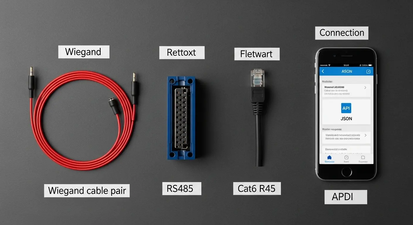
The Three Wiring Protocols: Wiegand, RS485, oraz TCP/IP
Choosing the right protocol for your turnstile gate wiring diagram affects cable run length, the number of devices on a single bus, and the depth of access event data available to the management platform:
Okablowanie protokołu Wiegand
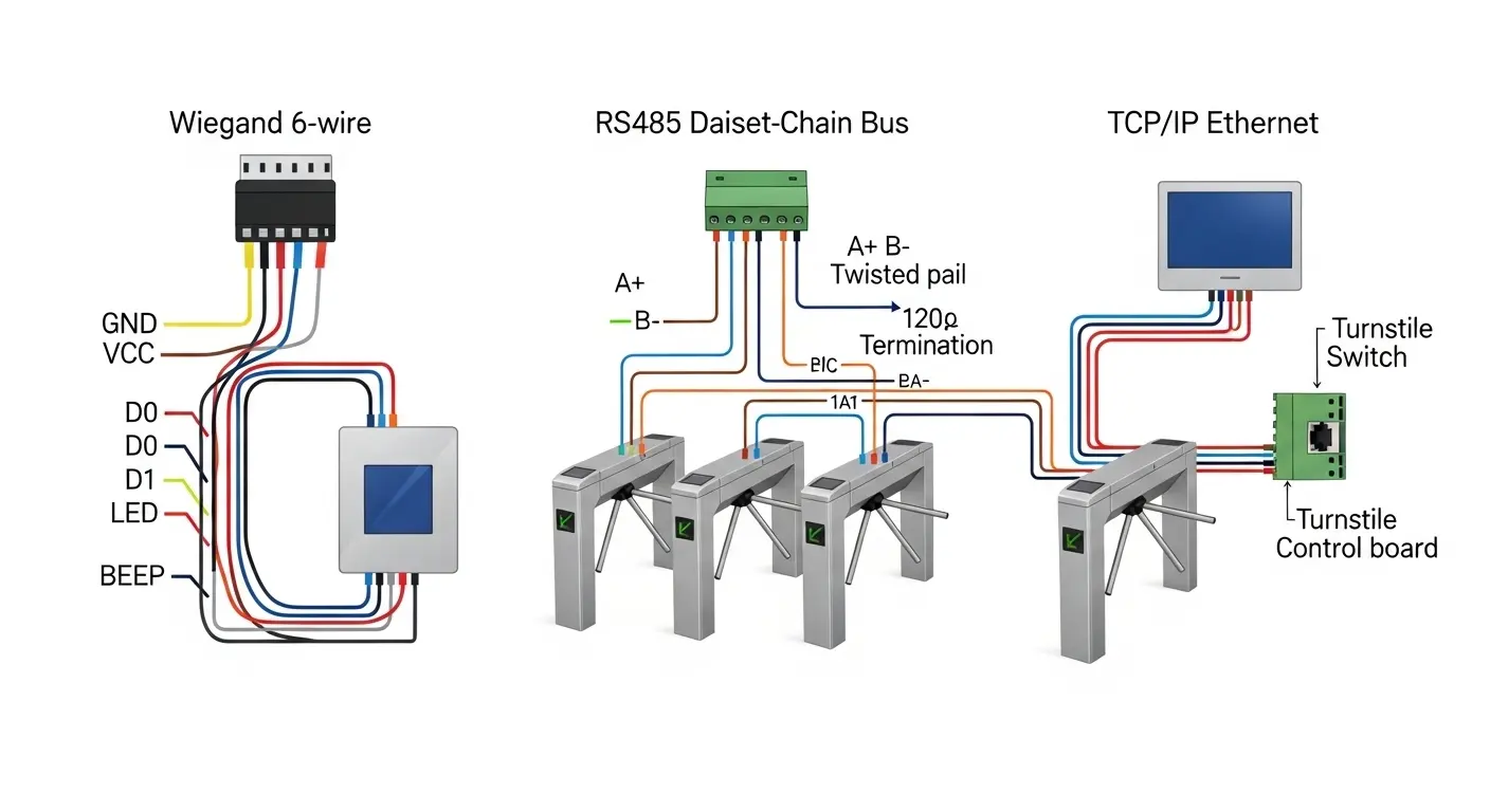
Wiegand is the oldest and most widely supported credential reader protocol. The reader connects to the access controller via a 6-wire Wiegand cable:
GND— Common groundVCC— 12V power supply (from control board internal PSU)D0— Data 0 (one data line of the differential pair)D1— Data 1 (second data line)LED— Reader LED control (green = access granted; red = access denied)BEEP— Reader buzzer control
Wiegand cable run limit: Maximum 150m between reader and access controller without a signal repeater. Beyond 150m, signal integrity degrades and the controller misreads card data.
Wiegand format: 26-bit is the most common standard format. 34-bit and 37-bit are extended formats used for larger card number ranges. Confirm the format compatibility between your reader and access controller before installation — mismatched Wiegand formats cause credentials to be rejected at the controller even though the reader reads the card correctly.
RS485 Protocol Wiring
RS485 is a two-wire differential bus protocol. Multiple devices — turnstile gates, czytniki kart, access controllers — share a single twisted-pair cable run.
Terminal connections:
A+(lubDATA+) — Positive differential signalB-(lubDATA-) — Negative differential signalGND— Common ground (connected at each device on the bus)
RS485 cable run limit: Up to 1,200m total bus length. Do 32 devices on a single bus without a repeater — making RS485 the correct protocol for multi-gate wiring in a single access control zone.
RS485 termination: The first and last device on an RS485 bus must be terminated with a 120Ω resistor across the A+ and B- terminals. Missing termination causes signal reflections at high baud rates — producing intermittent read failures that are extremely difficult to diagnose without a bus analyzer.
Dlaspeed gate turnstile with RFID installed in a multi-lane lobby, RS485 is the correct wiring protocol — one cable run connects all gates in the lane group to a single access controller, simplifying both installation and ongoing network management.
TCP/IP Protocol Wiring
TCP/IP connects the turnstile gate's control board directly to the building network — the same LAN as computers, IP cameras, oraz systemy zarządzania budynkiem. Connection is via an RJ45 Ethernet port on the control board.
TCP/IP advantages: Unlimited cable run length (via network switches), real-time event streaming to management software, remote configuration and diagnostics, and direct integration with cloud-based access management platforms.
TCP/IP considerations: Requires a network port at each gate position — coordinate with the IT team during installation planning. The control board needs a fixed IP address assigned from the building's network management system. Confirm the control board's firmware TCP/IP stack is compatible with the access management platform's communication API before installation.
Turnstile Gate Wiring Diagram by Gate Type
Not all gate types use identical terminal layouts. Here's how the wiring diagram changes across the main gate categories:
Flap Barrier Gate Wiring Diagram
A flap barrier gate has two panel drive mechanisms — one per side — each with its own motor driver circuit on the control board. The wiring diagram for a flap barrier therefore shows:
- Two motor output terminal groups (left panel motor and right panel motor)
- Two infrared sensor input arrays (entry sensor array and exit sensor array)
- Anti-pinch sensor input (separate from the passage detection sensor array)
- Indicator LED output terminals (mounted on the cabinet top cap)
- Reader input terminal (for the entry-side credential reader)
- Open signal input (for access controller connection)
- Emergency release input (for fire alarm connection)
DlaWysokowydajna brama barierowa z klapami with 10–16 infrared sensor pairs, the sensor wiring runs through a multiplexed sensor bus rather than individual terminal pairs for each sensor — confirm the sensor wiring architecture with the manufacturer before installation, as the connection method differs from basic 4–6 pair configurations.
AnBariera z klapą kontroli dostępu in a standard office deployment uses the Wiegand reader connection at 850mm ergonomic height, the open signal wired from the access controller's relay output, and the fire alarm dry contact wired from the building's fire alarm panel relay — a straightforward three-source wiring configuration.
Swing Barrier Gate Wiring Diagram (Brushless Motor)
A brushless motor swing barrier gate has a fundamentally different motor wiring configuration from a standard DC motor gate. The brushless motor requires three-phase motor output from the brushless motor driver circuit on the control board — not a simple two-wire DC motor connection:
Motor terminals:
U,V,W— Three-phase motor output from the brushless motor driverHall A,Hall B,Hall C— Hall effect sensor feedback signals (from motor to controller — do not reverse polarity)Hall VCC— Hall sensor 5V power supply from the controllerHall GND— Hall sensor ground
Critical installation note: The Hall effect sensor feedback wires from a brushless motor must connect to the correct terminals — Hall A to Hall A, Hall B to Hall B, Hall C to Hall C. Swapping any two Hall sensor connections causes the motor to run in reverse or fail to start at all. The motor phases (W, V, W) can be swapped in pairs to reverse the rotation direction without Hall sensor reversal — this is the correct method for adjusting barrier arm rotation direction in a brushless motor gate.
ABezszczotkowa bariera obrotowa silnika requires this specific motor wiring sequence — the brushless motor driver on the control board is pre-configured at the factory for the installed motor, making it critical to request the motor-specific wiring diagram from the manufacturer rather than using a generic swing barrier wiring diagram.
Wiring the Turnstile Gate to an Access Control System
This is the most frequently confused wiring step — and the source of most commissioning faults on turnstile gate installations:
Krok 1 — Identify the Open Signal Interface
The access control system communicates "access granted" to the turnstile gate through one of three methods:
- Dry contact relay: The access controller closes a relay contact, which connects the gate's open signal terminals together and triggers a passage cycle. This is the most universal method — works across all access control platforms and all turnstile gate control boards
- 12V trigger signal: The access controller outputs a 12V pulse on access granted, which the gate's control board reads as an open signal. Compatible only with control boards that accept voltage trigger inputs — confirm before wiring
- RS485 or TCP/IP command: The access management software sends an open command directly to the gate's control board over the network. This method is used in integrated systems where the gate and access controller are from the same platform
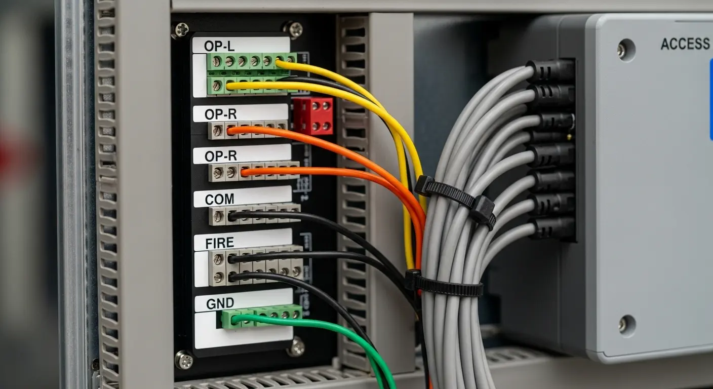
Terminal labels to connect:
- Gate side:
OP-L(open signal left direction),OP-R(open signal right direction),COM(common ground for open signal) - Controller side: Normalnie otwarte (NIE) relay contacts on the access controller output
Krok 2 — Wire the Credential Reader
After installing the reader at the gate cabinet's designated reader aperture, run the reader cable to the access controller. For Wiegand readers: GND, VCC, D0, D1, LED, BEEP. For RS485 readers: A+, B-, GND. Do not connect the reader data cable directly to the turnstile gate control board unless the gate has an integrated access controller board — most standard turnstile gate control boards control the gate mechanism but do not process credentials independently.
Krok 3 — Connect the Fire Alarm Dry Contact
The fire alarm relay output from the building fire alarm panel connects to the gate's emergency release input terminals. Most control boards label these terminals as FIRE iCOM (wspólny). When the fire alarm relay closes (lub otwiera, depending on the fail-safe or fail-secure setting), the gate releases all barriers to free passage — maintaining fire egress compliance.
Fail-safe vs. Zabezpieczenie w awarii:
- Awaryjny (power fail open): Gate releases on power loss or fire alarm — used at emergency egress routes
- Fail-secure (power fail locked): Gate remains locked on power loss — used at high-security perimeter access points where an open barrier creates a security risk
Confirm the gate's fail behavior setting matches the building's fire safety plan before commissioning.
Cable Specifications and Conduit Requirements
Correct cable selection prevents the most common post-installation failures — signal interference, voltage drop, and moisture ingress in underground conduit runs:
Power supply cable:
- 3-core, 1.5mm² minimum for runs up to 20m
- 3-core, 2.5mm² for runs of 20–50m
- Always include the earth/ground core — do not omit the earth wire on any power cable run
Reader data cable (Wiegand):
- Screened/shielded twisted pair, minimum 6-core (for full Wiegand connection including LED and BEEP)
- The screen/shield connects to GND at the reader end only — not at both ends (double-end shield grounding creates a ground loop that introduces interference)
RS485 bus cable:
- Screened twisted pair, characteristic impedance 120Ω
- Terminate with 120Ω resistors at both ends of the bus
- Maximum cable length 1,200m total bus
Conduit requirements:
- PVC conduit minimum diameter 3/4" (20Mm) for data cables, 1" (25Mm) for combined power and data runs
- Burial depth minimum 60mm below final floor surface for indoor installations; 600mm below grade for outdoor buried runs
- Conduit exit point must be bent back 180° to prevent water entry — the "swan neck" lub "J-bend" exit detail at the gate base
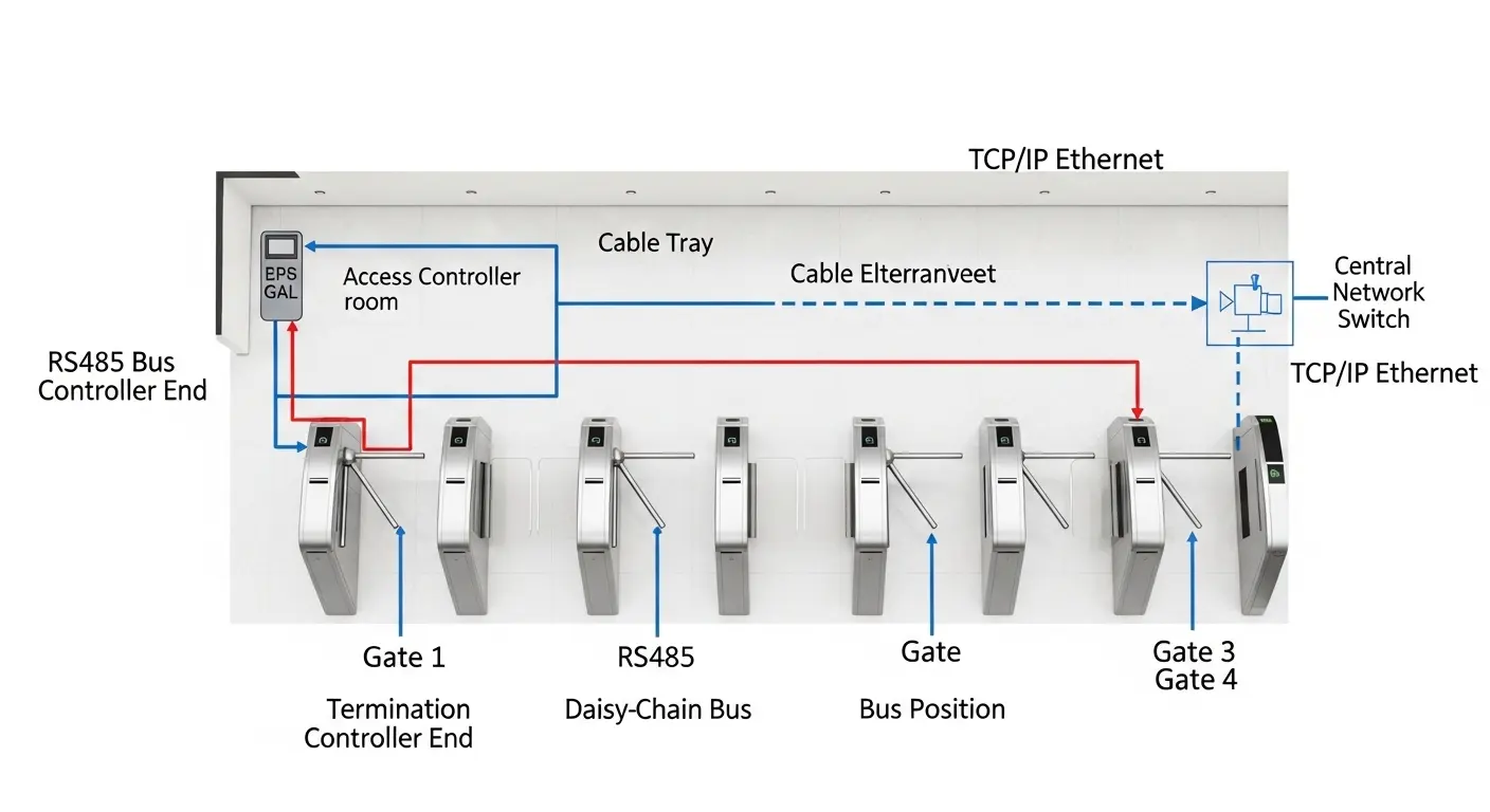
Multi-Gate Network Wiring
For installations with multiple turnstile gates — a lobby with 4–8 lanes, for example — the wiring diagram expands from a single-gate connection to a multi-device network:
RS485 Multi-Gate Bus Wiring
All gates connect to a single RS485 bus in a daisy-chain topology:
- Brama 1: A+ → A+, B- → B-, GND → GND (to access controller)
- Brama 2: A+ connected to Gate 1's A+ bus, B- to Gate 1's B- autobus
- Gate 3–N: Same daisy-chain continuation
- Last gate on the bus: 120Ω termination resistor across A+ and B-
- Brama 1 (at the access controller end): 120Ω termination at the access controller RS485 output
Each gate on the RS485 bus must have a unique device address set on the control board's DIP switches or through the configuration interface. Duplicate addresses on the same bus cause communication conflicts — both gates respond to commands addressed to that number, resulting in unpredictable behavior.
TCP/IP Multi-Gate Network
Each gate connects to a network switch via RJ45. Each gate control board needs a unique IP address on the building LAN. The access management software communicates independently with each gate's IP address — no daisy-chain topology required. This approach is simpler to fault-diagnose (each gate's network status is independently visible on the IT network) but requires a network port at each gate position.
Frequently Asked Questions About Turnstile Gate Wiring Diagrams
Q: What is a turnstile gate wiring diagram?
A: A turnstile gate wiring diagram is the circuit connection map showing how the gate's control board connects to all external systems — the power supply, the credential reader, the access control platform, the fire alarm panel, and any auxiliary inputs or outputs. It shows terminal labels, cable types, polarity, and the sequence of connections required to commission the gate correctly. The manufacturer provides a specific wiring diagram for each gate model and control board version — always use the diagram for your exact model, not a generic version.
Q: What is the difference between Wiegand and RS485 wiring on a turnstile gate?
A: Wiegand is a 6-wire point-to-point connection between one reader and one access controller. It supports a maximum cable run of 150m and one device per connection. RS485 is a 2-wire (plus ground) bus protocol that supports up to 32 devices on a single cable run of up to 1,200m. For single-lane installations, Wiegand works well. For multi-lane installations where multiple gates connect to a single access controller, RS485 is the correct protocol because it reduces cable infrastructure significantly.
Q: Why does my turnstile gate not respond to card credentials after wiring?
A: The five most common causes after installation: (1) Wiegand cable connected to the gate control board instead of the access controller — the reader cable goes to the controller, not the gate; (2) D0 and D1 wires swapped — swap them and test again; (3) Wiegand format mismatch between reader and controller (26-bit vs. 34-bit); (4) Open signal wiring from access controller to gate control board not connected or polarity reversed; (5) Power supply to the reader not connected — the reader needs 12V from the gate's internal PSU to function. Work through each cause systematically with the wiring diagram in hand.
Q: What cable should I use for a turnstile gate installation?
A: For power supply: 3-core 1.5mm² screened cable for runs up to 20m; 2.5mm² for 20–50m. For Wiegand reader data: 6-core screened twisted pair, screen connected to GND at the reader end only. For RS485 bus: 120Ω characteristic impedance screened twisted pair, terminated at both bus ends. Bury all conduits at minimum 60mm depth indoors and 600mm depth for outdoor underground runs, using PVC conduit with a swan-neck exit at the gate base to prevent water ingress.
Q: How do I wire multiple turnstile gates together on RS485?
A: Connect all gates in a daisy-chain topology — each gate's A+ and B- terminals connected to the same bus wire running from the access controller. Set a unique device address on each gate's control board DIP switches before connecting to the bus. Install a 120Ω termination resistor at both ends of the bus — at the access controller RS485 output and at the last gate on the chain. Use a maximum of 32 devices per bus segment without a repeater, and keep total bus length below 1,200m.